






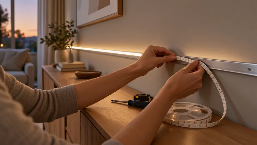
How to install LED strip lights comes down to three jobs done in the right order: plan the run, get the wiring and power right, then fix the strip to a surface that will hold it. The order is the method. Join and power the strip while the backing liner is still on, watch every section light, and only then press it to the wall.
The costly mistake in this job is sticking too early: a strip bonded under a cabinet before anyone switched it on turns a loose clip into a removal job. The formats we build sit in our LED strip lights range, but the sequence suits any low-voltage tape, and it is the one a retail buyer should see printed in the carton.
Key takeaways
Plan on paper, finish every wire, light the run with the liner on, then mount it.
- Light the whole run before the backing comes off, then bond it, clip the ends and power it for real.
- Same DC voltage, plus to plus, and about 25% more supply capacity than the strip draws.
- On an assumed 48 W load, 18 AWG feed wire reaches about 5.7 ft at 12 V before losing 3% of the voltage, and 22.6 ft at 24 V, computed from NEC Chapter 9 Table 8.
- A Class 2 supply is capped at 100 VA at 30 V or less, so big installs split into several feeds.
- Pressure-sensitive tape reaches about 90% of its bond after 24 hours on one 3M foam tape, so leave new runs unloaded overnight.
How to Set Up LED Strip Lights on Paper Before Anything Is Stuck
To set up LED strip lights, draw the run before you buy or cut anything: where the light goes, where the supply lives, how the cable gets between them, and how many pieces the line breaks into. That sketch is the parts list, and it shows early whether the job is a plug-in afternoon or a hardwired one that needs an electrician.
Start with the strip type, because it decides the wire. LED strip lights most commonly run on 12 or 24 volts DC, and the pads at each cut point follow the colour channels: two on single colour, three on tunable white, four on RGB and five on RGBW (Wikipedia). Every lead and joint carries one conductor per pad. Addressable strips such as our RGBIC music-sync strip add a data line, and on addressable tape the controller connects at the end the printed arrows point away from.
Then put the supply somewhere it can be reached. Where a driver meets mains wiring the connection sits in a box, and NEC section 314.29, as worded through the 2017 edition, required that wiring to be accessible without removing any part of the building; EC&M columnist Russ LeBlanc noted in 2024 that the 2020 edition split it, with 314.29(A) covering boxes in buildings. Write two numbers on the sketch for every segment: strip length, which sets the wattage, and lead length, which sets the voltage lost on the way.
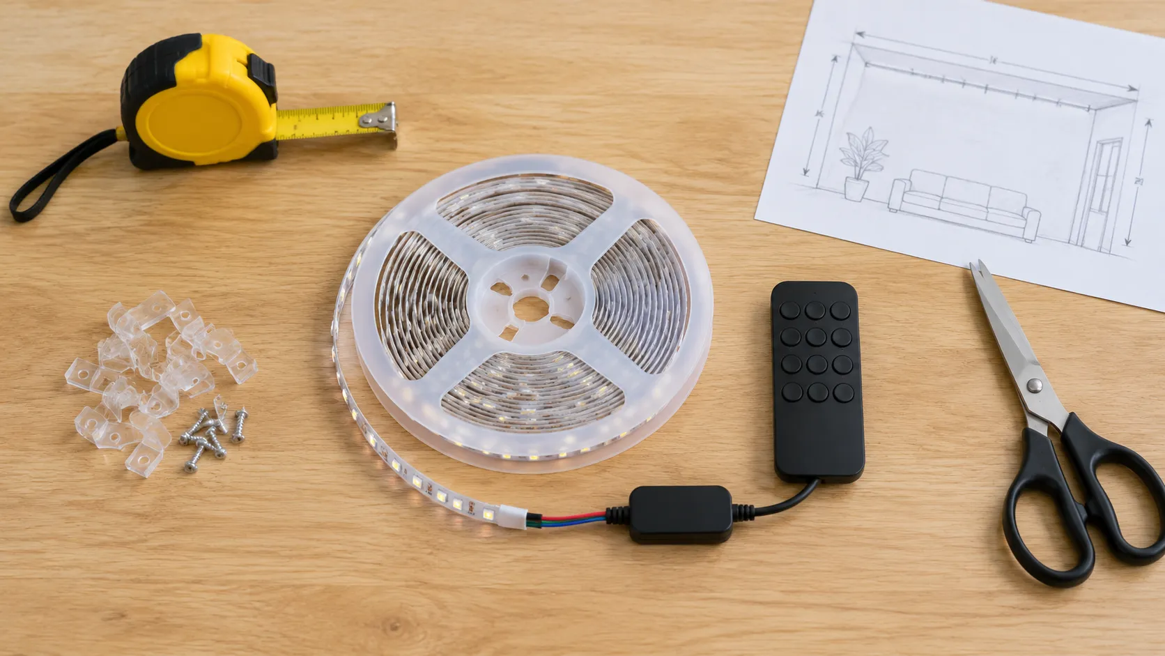
| Item | Must match | Confirm with the supplier |
|---|---|---|
| Strip | The sketch; cut only on the marks | Watts per metre, voltage, cut spacing (quote items on our lines) |
| Supply or plug-in adapter | Strip voltage, with headroom | Whether one ships in the kit |
| Controller and remote | Pad count and data line | Which ones the kit carries |
| Leads and connectors | Distance, strip width, pad count | Lead length, connector type and count |
| Clips and channel | The mounting surface | Packed only if written on the order |
| Tools | Tape measure, scissors, wire stripper, screwdriver, multimeter | Installer side |
The table leaves out the listing. UL 2108 revisions in effect for new submittals and revised products from 6 December 2021 make field-cuttable Class 2 luminaires repeat certain markings at intervals (UL Solutions), but those markings exist only on listed product, so a buyer who needs a listing should ask the supplier for the listing file in writing rather than infer it from the carton.
The job then runs in six steps, each closing a question before the next one makes it expensive to reopen.
Draw the run
Segments, corners, supply position and cable route, with strip and lead lengths kept apart.
Place the supply
Ventilated and reachable; its distance picks the wire gauge.
Cut and join on the bench
On the marks only, every pad matched.
Light it with the liner on
Lay it flat, connect it, check every section and channel.
Bond, clip, then power
Clean, press the full length, clip the ends and corners, then switch on for good.
Dress and label
Clip the leads, label each supply, leave the spare connectors.
How to Wire LED Strip Lights: Polarity, Voltage and Run Length
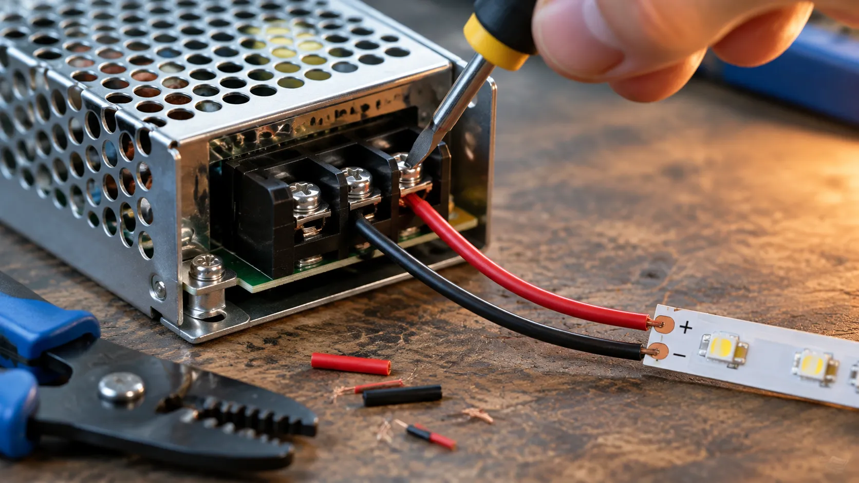
To wire LED strip lights, connect positive to positive and negative to negative, use a supply at the strip’s DC voltage, and size the feed wire for its distance. Waveform Lighting notes that positive is usually red and negative black or white, and that undervoltage leaves a strip dim or dark while overvoltage burns out the LEDs (Waveform Lighting). Colours are only a convention, so read the + printed on the pads.
Distance is where wiring fails quietly, because every foot of lead is resistance, counted out and back. NEC Chapter 9 Table 8 gives 7.95 ohms per 1,000 feet for stranded 18 AWG copper at 75°C, and IAEI Magazine notes that the standard voltage drop formulas are built on those values (IAEI Magazine). A sensible target is 3%: the NEC informational notes recommend it for a branch circuit, and EC&M’s Mark Lamendola points out that it is advice, not a code requirement. On a 12 V strip, 3% is 0.36 V.
Source: computed from NFPA 70 Chapter 9 Table 8 resistances and the 3% informational-note target reported by EC&M; length = 3% of voltage ÷ (2 × current × ohms per foot); checked 2026-10-12
Voltage beats gauge. At the same wattage a 24 V circuit draws half the current, so the same wire carries it four times as far. A 20 ft lead of 18 AWG on that 48 W load drops about 1.27 V, or 10.6% of a 12 V supply; at 24 V it drops 0.64 V, or 2.7%. The 12 V run still lights. It just looks tired from end to end, and the customer blames the strip.
Every cut is a future joint, so cut only on the printed marks; rejoining a cut strip by clip or by solder is section 04 of our guide to cutting LED strip lights.
How to Connect LED Strip Lights Together: Clip Connectors, Jumpers or Solder
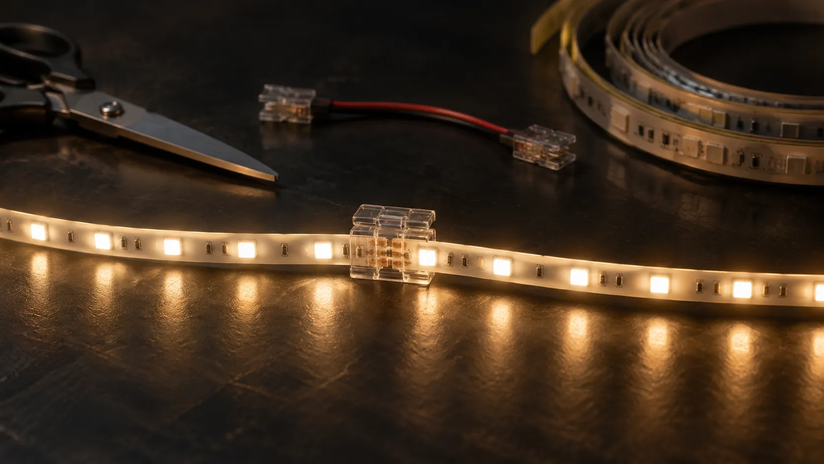
Connect LED strip lights together with the joint that matches what the two ends are, not whichever connector came in the bag.
- Supply to strip: a lead with a clip at one end. It carries everything downstream, so it gets the heaviest wire.
- Across a gap or corner: a short length of wire with a clip at each end, which bridges the gap without bending the strip. Each one adds two contact points.
- End to end: a straight splice, quickest to fit and the easiest to knock loose while pressing the run down.
- Solder, for any of them: permanent, and the answer where a clip will not fit or the joint will be hidden for good.
Most people asking how do you connect LED strip lights together are holding two of those at once, usually a corner and a run that came up short. A clip must match the strip’s width and pad count; one made for wider tape grips one pad, barely touches the next, and flickers a week later behind a cabinet.
The bigger decision is how the pieces get back to the supply. Chaining reel after reel off one feed breaks single-feed limits, because the strip’s own copper drops voltage too. Our under-cabinet buyer primer puts that limit at roughly 16.4 ft (5 m) on 12 V and 32.8 ft (10 m) on 24 V, citing Super Bright LEDs. Beyond it, wire each segment back to the supply in parallel, or feed both ends. For our strips the single-feed length is a quote line, not a catalogue claim.
Outdoor tape needs one more step: a coated strip loses its seal where it is cut, so the end gets a cap and sealant. Our outdoor waterproof LED strip comes in 10 m and 20 m lengths, and its exact ingress rating, along with whether a cut end keeps it, is confirmed per order.
How to Connect LED Strip Lights to Power Supply Units and Test Before Mounting
Connect LED strip lights to a power supply only after three checks: DC output at the strip’s voltage, headroom over the load, and positive to positive at the terminal or plug. Then light the whole run before any backing comes off.
Add up the strip’s draw, watts per metre times metres of strip with the leads left out, and pick a supply about 25% larger, the divide-by-0.8 rule worked through in our kitchen strip guide. Round up, never down: 48 W of strip needs at least a 60 W supply. Big installs hit a second ceiling. A Class 2 source is limited to 100 VA for circuits at 30 V or less, according to Mike Holt’s summary of NEC Article 725 in EC&M, so a larger design splits across two or more supplies, each feeding its own segments.
Most guides to how to connect LED strip lights stop at the plug, and for many shoppers that is the whole job. For them, how to install LED lights under a cabinet means a plug-in kit such as our under-cabinet motion LED strip kit, which runs from a low-voltage adapter and switches by Motion, Touch or Always-On; pack contents are specified per program.
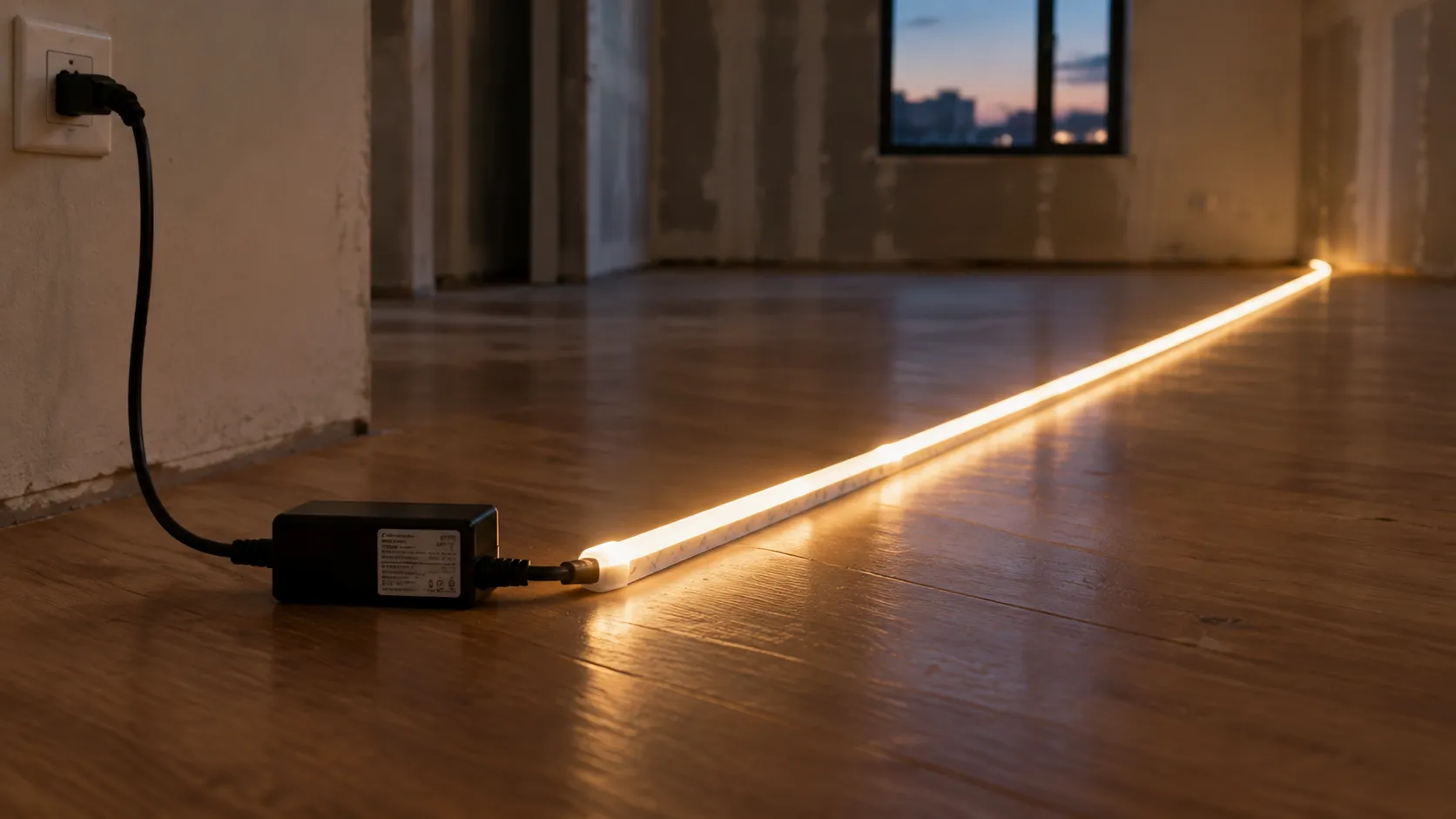
The test needs no tools. Lay the run flat where it will go, liner on, connect it and walk it: every segment lit, no dark section after a joint, the far end matching the near end, every colour channel working. Switch off. Then clean, press, clip the ends and corners, and power it for good. Our double-sided tape guide covers the bond-and-clip half of this order; the light test belongs at its dry-lay step, while the liner is still on.
How to Hardwire LED Strip Lights, and When It Is an Electrician Job
To hardwire LED strip lights, a licensed electrician connects the driver to the mains under the NEC and local rules, and the low-voltage strip then runs from that driver like any plug-in kit. The 120 V side is not DIY work and may need a permit where you are, so this guide stops at the driver’s output terminals.
What the buyer and installer can settle first is the layout: a reachable driver location, a switch or dimmer the driver is designed for, and cable rated for where it runs. Class 2 cable has to be listed and installed to sections numbered 725.133, 725.135 and 725.154 in the same EC&M summary from December 2016; check them against the code edition your jurisdiction enforces. Whether a retail range needs a hardwired version at all is weighed in our under-cabinet primer; the electrician’s visit can cost more than the strip.
Hand the electrician a one-page sheet before the visit: each driver’s location, its input and dimming type from the label, the strip load it carries, and where each low-voltage lead leaves the wall. Once the driver shows the right DC output, the rest follows this guide, and the written hand-off later shows whether a complaint belongs to the strip or the house wiring.
How to Install LED Strip Lights on Wall Runs and Around Corners
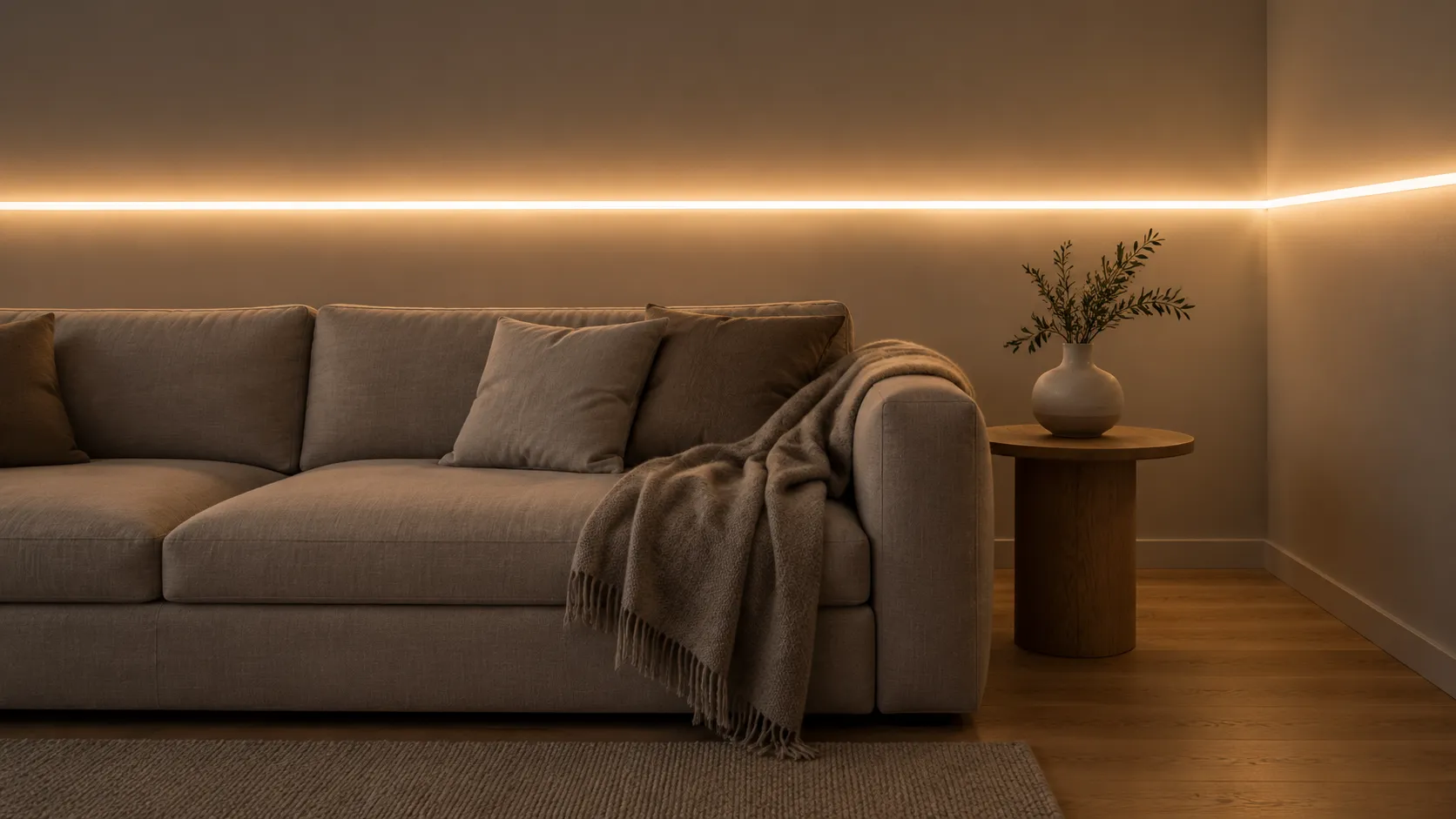
To install LED strip lights on wall runs, mark a level line, bring the feed to its start before any tape goes up, and decide at each corner whether the strip bends or gets a joint. A run that drifts a few millimetres over a sofa reads as crooked from across the room.
Most people asking how to put up LED strip lights mean exactly this wall. Strip bends easily on its flat face, so a run going round the corner from one wall to the next follows it, given a radius rather than a crease. It does not bend edgewise, in its own plane, without straining the copper and the LED joints. Turning from horizontal to vertical on one wall, around a window or up a door frame, is edgewise: cut at the nearest mark and bridge it with a jumper or an L connector. Clip every corner, because that is where peel starts.
The wall decides the fixing before the tape does, and our guide to LED strip lights with double-sided tape grades painted board, textured paint, brick and timber, with the carton hardware each one needs. Where a wall will not take tape, or the line must look architectural, an aluminium profile from our LED channel guide does the job.
How to install LED strip lights in ceiling coves is mostly about hiding the source, covered in our guide to ceiling strip runs. Whatever the wall, clip the exposed lead or run it in a surface raceway, never staple through it, and keep the slack near the supply.
How to Hang LED Strip Lights So They Do Not Peel Off in a Month
To hang LED strip lights so they stay up, clean the surface with an alcohol and water mix, apply them in a warm room with firm pressure along the full length, clip the ends and corners, and leave the run unloaded overnight. Strips fall off for a short list of reasons: dust or grease, a cold or textured surface, free ends, and heat.
Most of the hold is decided as the liner comes off. Peel a hand’s length at a time and press as you go, in one direction from end to end, so air is pushed ahead of your thumb rather than trapped as blisters, each one a patch of strip held by nothing. Keep fingers off the exposed adhesive; skin oil does what grease on the wall does.
Two surfaces need their own prep. Wipe the inside of an aluminium channel with alcohol too, since an extrusion fresh from the saw can carry cutting oil and swarf. Silicone-coated or silicone-sleeved waterproof strip is what factory backing handles worst, because ordinary acrylic adhesive grips silicone poorly; hold those runs with clips or a channel, or with an adhesive rated for silicone.
Pressure-sensitive backing builds its bond over a day: 3M’s data sheet for VHB Tape 5925, revised September 2024, reports about 90% of ultimate bond after 24 hours (3M). Strip backing is rarely that grade, and on our lines the adhesive grade is agreed against a sample, so take the curve as how the adhesive family behaves rather than as a rating, and leave a new run unloaded overnight.
The 2019 UL 2108 revision also requires the instructions of Class 2 luminaires with mounting means judged unreliable to warn against installing them where failure could injure someone or damage property (UL Solutions). Over a bed, a stair or a doorway, use mechanical fixings.
Troubleshooting: What You See, What Causes It, What to Check
Most faults appear at the first power-on and trace to a joint, the supply or the feed wire, so check upstream before downstream and free checks before the meter. Each row starts with what you can see.
| What you see | Usual cause | What to check, in order |
|---|---|---|
| Far end dimmer or warmer than the near end | Lead too thin or long, or one feed driving too much strip | Measure volts at the supply and at the strip end; fit a heavier lead, feed both ends, or split into parallel segments |
| Nothing lights | No mains, wrong voltage, reversed polarity, loose first joint | Test the socket with a lamp; confirm the supply label reads DC at the strip’s voltage; check plus to plus; reseat the first connector |
| One section dark or the wrong colour | Clip not seated, cut off the mark, channel wire swapped | Reseat that joint; check the cut; match every channel letter |
| Flicker | Loose joint, supply near its limit, dimmer and driver mismatch | Reseat joints; compare watts with the rating; test without the dimmer |
| Switches itself off and on | Overload, or a low-voltage short such as a pinched lead, tripping the supply’s protection | Unplug; look for a pinched lead or damaged pads; compare the watts with the rating and split any overload |
| Breaker or GFCI trips | A fault on the mains side: wet outdoor plug or socket, damaged adapter or driver input | Disconnect; do not keep resetting; call an electrician if it repeats |
| Strip peels or falls down | Dust or grease, cold or textured surface, free ends, heat | Clean with alcohol and water, re-press, clip the ends and corners |
Flicker that only shows while dimming is a compatibility fault; the kitchen strip guide gives a ten-minute diagnosis order for it. Outdoor jobs add one check before the first row. Most outdoor lighting systems run off a low-voltage AC transformer, usually 12 V AC, while LEDs need direct current (LEDSupply), so a DC strip goes on a DC supply or behind a driver that converts the transformer’s output, never straight onto the landscape circuit.
The table also screens returns: ask which row the customer saw before testing the strip, because often it is a joint, a supply or a surface.
For a retail buyer, the output of all this is a short spec and a short insert: voltage, single-feed length, supported joints, carton contents and the install order above. Every format in our LED strip lights line is quoted against those lines.
Have the strip, the kit and the insert specified together
We build LED strip in our own factory in Foshan, 4,000 square metres with 40 people across two production lines. Send the run lengths, the voltage and the control your shoppers expect, and we will confirm watts per metre, cut spacing and carton contents against your brief.
Watch it work
Why a strip stuck under a shelf before anyone switched it on turns into a removal job, and the order that avoids it, in 38 seconds:
FAQ
How to install LED strip lights without damaging wall?
Keep the adhesive off the paint. Stick the strip to a thin aluminium channel or a painted batten, and hold that up with removable picture-hanging strips or two small screws that leave pin-sized holes. To take down a strip already on paint, warm the tape with a hair dryer on low, peel it back along the wall at a shallow angle instead of pulling outward, and roll off residue with a thumb before trying any solvent.
How to connect LED strip lights to 12V power supply?
Read the label first: the output should say 12 V DC, with rated watts above the load of the strip, not level with it. With the supply unplugged, find the output terminals, usually marked V+ and V- or + and COM, and land positive on V+ and negative on V-. If the supply ends in a barrel plug, a screw-terminal barrel adapter does the same job once its plus marking matches the polarity symbol on the supply. Tug each wire, then plug in.
How to install LED strip lights on wall corner?
Outside and inside corners behave differently. On an outside corner, such as a chimney breast, the strip wraps with a gentle radius and a clip a hand width either side stops it springing off. For an inside corner, pre-bend the strip before the liner comes off and push it into the angle with a blunt plastic tool, not a fingernail. For a crisp corner with no bend at all, use two mitred channel pieces with a short jumper inside.
How to connect LED lights together without connector?
Solder them; cutting, tinning and heat-shrink work as in any soldered repair. Two cases need more. Across a gap or an edgewise turn, bridge each pad pair with a short piece of stranded wire, which flexes with the strip instead of levering on the pads. On addressable tape the data wire runs from the output pad of one piece to the input pad of the next, in the direction the printed arrows point. Twisted bare wires wrapped in tape are not a joint, even temporarily.
Sources
Every external figure above was checked on 2026-10-12: conductor resistance from the NEC table itself, the voltage drop basis and recommendations from IAEI Magazine and EC&M, Class 2 limits and box accessibility from EC&M code columns, product-standard changes from UL Solutions, adhesive behaviour from a 3M technical data sheet, outdoor transformer output from a trade supplier’s retrofit note, and strip voltages, pad counts and polarity conventions from the remaining references.
- NFPA 70, National Electrical Code, 2017 edition, Chapter 9, Table 8, Conductor Properties (direct-current resistance at 75°C of stranded uncoated copper: 18 AWG 7.95, 16 AWG 4.99, 14 AWG 3.14, 12 AWG 1.98 and 10 AWG 1.24 ohms per 1,000 ft; backs the resistances and the computed chart), record checked 2026-10-12.
- IAEI Magazine, Voltage Drop Formulas, 2017 (voltage drop formulas based on Chapter 9 Table 8 dc resistance values at 75°C, k of 12.9 for copper; backs the method behind the chart), retrieved 2026-10-12.
- EC&M, Mark Lamendola, Watch Out for That Voltage Drop, 2015 (3% for a branch circuit and 5% combined, given in informational notes rather than as NEC requirements; backs the 3% design target), retrieved 2026-10-12.
- EC&M, Mike Holt, Article 725, Class 2 and 3 Circuits, December 2016 (Class 2 limited to 100 VA at 30 V or less; Class 2 cables listed and installed to 725.133, 725.135 and 725.154; backs the Class 2 ceiling and cable notes), retrieved 2026-10-12.
- EC&M, Russ LeBlanc, Practically Speaking: Let’s Dig into Sec. 314.29, 2024 (through the 2017 edition, Sec. 314.29 required wiring in boxes to be rendered accessible without removing any part of the building, and the 2020 edition split it, with 314.29(A) applying to boxes in buildings; backs the reachable driver location), retrieved 2026-10-12.
- UL Solutions, Michael Shulman, Opportunities and Impacts of Revisions to UL 2108 (Standard for Low Voltage Lighting Systems), 2019 (revisions published 6 December 2019 and in effect for new submittals or revised products as of 6 December 2021; repeated markings on field-cuttable Class 2 luminaires; installation instructions for all luminaires; caution statement for unreliable mounting means; backs the listing note under the parts table and the mounting warning in the hanging section), retrieved 2026-10-12.
- 3M, Technical Data Sheet, 3M VHB Tape 5925, last revised September 2024 (bond builds with dwell time, about 90% of ultimate strength after 24 hours; isopropyl alcohol and water as the cleaning step; backs the overnight wait in the hanging section), retrieved 2026-10-12.
- Wikipedia, LED strip light (strips most commonly operate on 12 or 24 V DC; pin counts of 2 for single colour, 3 for tunable white, 4 for RGB and 5 for RGBW; backs the voltage and pad-count line), retrieved 2026-10-12.
- Waveform Lighting, How to Connect an LED Strip to a Power Supply (positive usually red, negative usually black or white; undervoltage dims or blanks a strip and overvoltage burns out LEDs; backs the polarity and voltage-matching lines), retrieved 2026-10-12.
- LEDSupply, Taylor Scully, Perfect LED Retrofit Solution for Landscape Lighting using a 12VAC Transformer, 6 February 2019 (most outdoor lighting systems run off a low voltage AC transformer, usually 12VAC; LEDs need direct current, so the 12VAC has to be converted for them; backs the outdoor transformer check under the fault table), retrieved 2026-10-12.
