



LED strip lights ceiling runs are drawn in section and bought in metres, and most of the ones that go wrong went wrong in the gap between those two facts. The reel turns up, the fascia is 40 mm shallower than the drawing assumed, and a line of light is handed over as a row of dots.
Three neighbouring questions belong on other pages. The same detail above kitchen wall cabinets, where joinery rather than plasterboard sets the geometry, is in our kitchen strip guide; profile families, diffuser grades and heat are in the LED channel guide, which is why the channel gets one sentence here rather than a section.
Colour temperature, fidelity, driver selection and supply sizing are decoded in our supplier spec decoder, and the formats we build sit in the LED strip lights range. What follows is the part no spec sheet covers: the three places tape goes on a ceiling, and how many metres the room will actually pay for.
Key takeaways
Spec led strip lights ceiling work from the section outward. Whether the source hides is settled by the sight line; how much light comes back depends on the ceiling finish; the energy allowance caps the metres a space can carry, and the corners are where the job gets judged finished or not.
- Indirect light is spent twice. ASHRAE and IES guidance assumes 80% ceiling reflectance in small retail and 90% where the scheme is indirect, so the paint schedule is a lighting line item.
- Published setback guidance disagrees on purpose: 18 inches (46 cm) below the ceiling buys an even wash on a surface people look at, a shallow ledge buys a glow at an edge nobody examines.
- The energy code sets the metre count before the designer does. A corridor is allowed 0.44 watts per square foot and a retail sales area 0.85; one watt per square foot is 10.76 W/m².
- A ceiling line cannot be the only light in a circulation space: egress illumination has to reach 1 footcandle (11 lux) at the walking surface, and 10 footcandles (108 lux) on exit stairways in use.
- Grazing light with people moving under it is where temporal light modulation shows, and some observers still see it at 1000, 2000 and even 6000 Hz.
What a Ceiling Run Has to Do That a Downlight Cannot
A ceiling run is not a brighter downlight. It is a line whose whole job is to make a surface look continuous, so it gets judged on the part of itself you can see least.
Point sources put light on the floor and leave the ceiling dark, so the ceiling reads as a lid. A cove or a cornice run inverts that geometry: the output lands on the ceiling or the upper wall first and returns to the room as one large, low-contrast source. That is why the detail survives value engineering in hospitality and retail fit-out: it changes the apparent height and quality of a plasterboard ceiling for less money than any fitting can. Buyers who type led strip ceiling lights into a search box mean that effect, not the hardware.
Every watt in an indirect scheme is spent twice, once going up and once coming back. ASHRAE and IES design guidance assumes 80% ceiling reflectance for small retail and 80% to 90% for offices, moving to 90% where the scheme is indirect (Craig DiLouie, LightNOW). One bounce off an 80% ceiling has already given away a fifth of the light, and a repaint in a greyer white can cost more output than a step up in tape will buy back.
Commercially, that run competes for a capped pot. Lighting took about 10% of total energy use in US commercial buildings in 2018 (U.S. Energy Information Administration), and the code caps what any one space may draw. A ceiling line is the decorative part of that load, so it has the weakest claim on the budget.
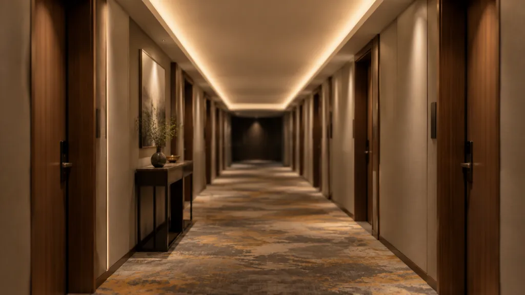
Ceiling Cove: Where the Light Has to Hide on a Hotel Corridor
The ceiling cove is the placement everyone pictures and the one with the tightest geometry: a ledge held away from the ceiling, tape aimed up, and a fascia tall enough to keep the source out of sight from anywhere a person can stand.
Published guidance on the setback disagrees with itself, and the disagreement is worth reading rather than resolving. The standard reference description of the technique, indirect light built into ledges, recesses or valances in a ceiling or high on a wall, puts the minimum distance from the ceiling at 18 inches (46 cm), with the cove around 6 feet 8 inches (2.03 m) off the floor (Wikipedia, Cove Lighting). Trade details routinely show ledges a fraction of that depth. Both are right for different jobs: the deep figure buys an even wash on a ceiling studied across a lobby, the shallow one a bright edge nobody examines.
Peer-reviewed work turned the rest of it into a procedure. Zagan, Skarzynski and Tryzna set out a simplified method for selecting cove equipment, working back from a room of known height and floor area to the luminous flux per metre the tape has to deliver for a target average illuminance at acceptable uniformity (Ain Shams Engineering Journal). For a buyer that matters less as arithmetic than as an order of operations: room dimensions set the lumens per metre, which set the watts per metre, which decide whether the run fits the energy allowance at all.
Run the hotel corridor case and the scale shows up. A 50 m corridor coved on both sides is 100 m of tape before a single guest room is lit, which is why corridors are where ceiling schemes fail their load calculation. The placement the trade files under led strip cove lighting is only one of three here, and its kitchen cousin above the wall cabinets is handled in our kitchen guide. Extrusion choice sits with the channel families; it makes the line neater and it does not rescue a badly drawn cove.
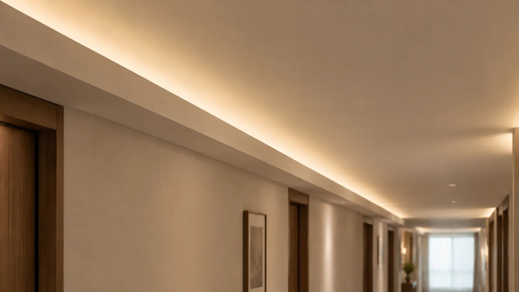
Hiding LED Strip Lights Starts at the Sight Line, Not the Channel
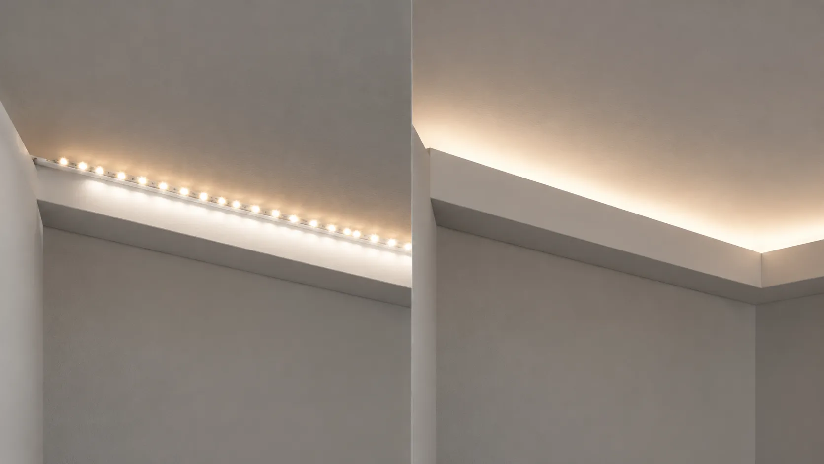
Hiding led strip lights is a geometry problem that hardware only finishes. Three conditions decide it, and all three are settled on the section before anyone orders a diffuser.
The first is fascia height against the lowest eye position in the room. Draw a line from eye height at the nearest point a person can stand to the top inner edge of the fascia and extend it; everything above that line is visible, so the tape sits below it. In a corridor the nearest standing point is almost against the wall, which is the worst case and the one a plan-only drawing forgets. The second is emitter setback from the inner face of the fascia, so the beam clears the lip instead of grazing it and printing a bright stripe on the plaster. The third is the distance from tape to lit surface, because near-field scallops have to land outside the zone anyone looks at.
Only then does hardware matter. An extrusion with a frosted cover blurs individual diodes into a line, at the cost of output, and it does nothing for a source sitting too high behind too short a fascia. Get the section wrong and the channel delivers an even, visible, expensive strip of dots.
One failure mode is specific to this placement and never shows in a showroom. Light grazing a surface with people walking under it is where temporal light modulation becomes visible. The U.S. Department of Energy places direct flicker roughly between 3 and 80 Hz and stroboscopic effects from about 80 Hz to 1000 Hz, and reports observers still identifying modulation at 1000, 2000 and 6000 Hz where eye and source are moving relative to each other (U.S. Department of Energy). Test a sample at the bottom of its dimming range with a hand sweeping under it.
Perimeter Drops, Stepped Cornices and the Wall Wash Off the Ceiling Line
Two more placements come off the same ceiling line and behave nothing like a cove, which is why quoting all three as metres of tape starts three different arguments on site.
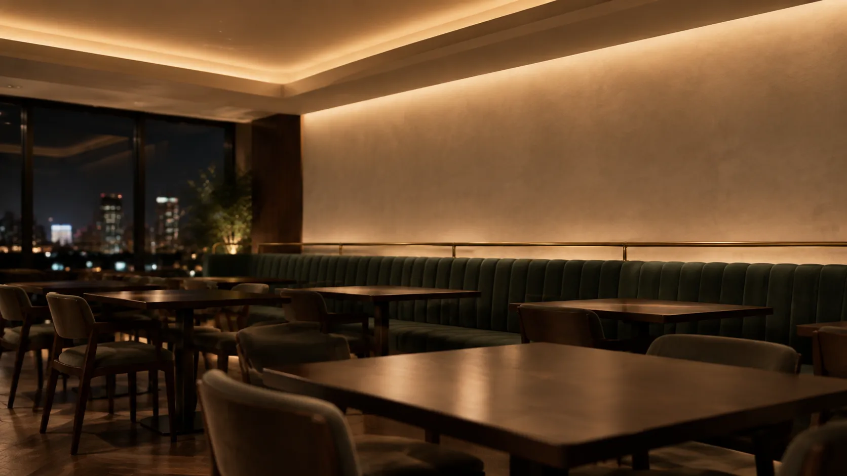
A stepped cornice or perimeter drop hides a change in ceiling grade around a room. Tape sits in the step, usually aimed up and outward, and step depth decides how much of the upper wall is lit alongside the ceiling. It flatters a level ceiling and punishes an uneven one, because a continuous line of grazing light is also a continuous measuring instrument for the plasterer. Where a seasonal run goes up on that same detail in November, the calendar and the kit are both different, and that case is in our Christmas strip stocking guide.
Wall washing off the ceiling line rotates the problem. The plane being lit is vertical, so setback from the wall rather than from the ceiling controls scalloping, and the aim tips away from the surface instead of along it. Specifiers use led strip wall lighting in two opposite ways that look identical on a quotation. Grazing, with the tape close to the wall, shows texture and suits brick, stone or fluted panelling. Washing, with the tape further out, flattens texture and suits painted plasterboard, where grazing turns every taped joint into a shadow. Settle which one the client has in mind before the drop is built: the difference is a hundred millimetres of setback and no tape selection fixes it later.
All three land on commercial accounts more often than homes, from hotel corridors and lobbies to restaurant perimeters, salon rooms and store fit-outs. How those accounts buy is covered in our notes on mood lighting for retail accounts. In housing the same line is one of four layers rather than the main event, the argument our bedroom lighting ideas page makes at length.
| Placement | What it lights | Hiding condition | Typical failure | What the order states |
|---|---|---|---|---|
| Ceiling cove, aimed up | The ceiling plane, returned as a soft source | Fascia above the sight line from the nearest standing point | Source visible at the room edge; stripe on the lip | Fascia height, setback, ceiling clearance, aim |
| Stepped cornice or perimeter drop | Ceiling plus the top of the wall, hiding a grade change | Step depth beyond the visible cone from the room centre | Level errors read as a wavy line of light | Step depth, finish either side, continuity |
| Wall wash from the ceiling line | A vertical plane, grazed for texture or washed flat | Setback from the wall, not from the ceiling | Grazing plasterboard and printing every taped joint | Graze or wash, setback, aim angle, wall finish |
Continuity: a Ceiling Line Is Judged on Its Dark Spots
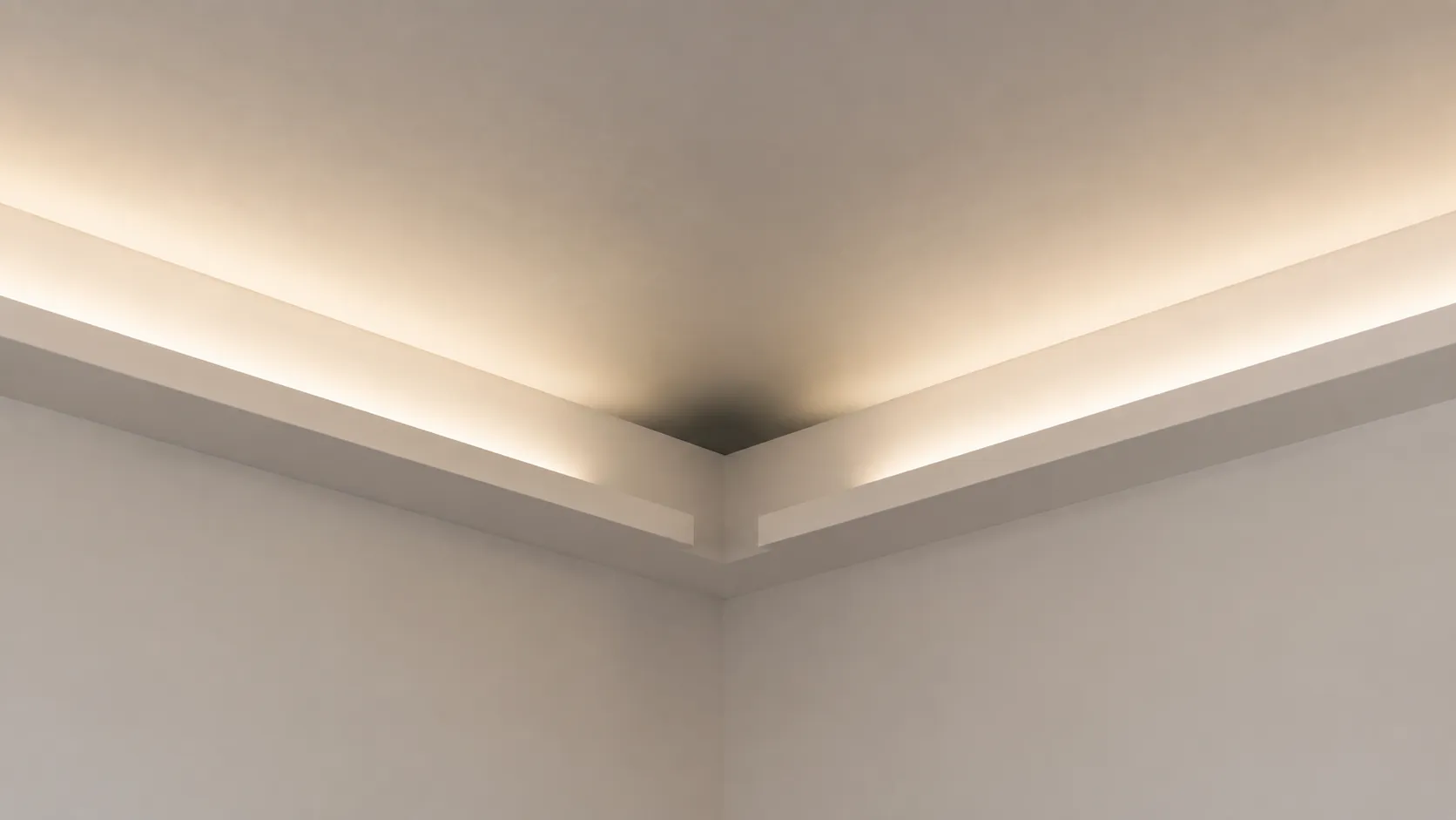
Nobody photographs the middle of a cove. They photograph the corner, and the corner is where a ceiling line reads as architecture or as a weekend job.
Four places break a line, and each is a decision taken on a drawing rather than on a ladder. Reel ends leave a seam wherever the cut schedule and the room dimensions disagree. Internal corners leave a dark wedge when two runs stop short of each other. Movement joints open, so a rigid run crossing one fails there first. And the fascia return at a doorway is where the source becomes visible from the threshold, the one view every guest gets.
Colour consistency is the second continuity problem. Assemble a long run from more than one production lot and the difference shows where the lots meet, at close range, not across the room. One bin per run is worth putting on the order: it costs the factory planning and costs the buyer nothing to ask. Repairs raise it again: ENERGY STAR defines LED lifetime as the moment output has fallen by 30%, so a run half replaced after a leak shows the new half as a step rather than a fade.
Heat is the quiet version of it. A cove is a sealed pocket with no airflow and often a timber or plaster surround, so a run that would sit cool on an open ceiling runs hot inside the detail drawn around it; what the extrusion does about that is in our LED channel guide. The decision that stays on this drawing is output per metre: in a tight pocket, specify less light per metre over a longer run rather than more out of a shorter one.
Watts Per Metre and the Allowance the Line Must Fit Inside
Metre counts on a ceiling job are not set by the designer. They are set by how much power the space is allowed to draw, and the tape competes with everything else in the room for it.
The energy code publishes that number space by space. A corridor is allowed 0.44 watts per square foot, a lobby 0.80, a retail sales area 0.85, a bar or lounge dining area 0.76 and a cafeteria 0.36, while the whole-building method gives a hotel or motel 0.53; one watt per square foot converts to 10.76 W/m² (International Energy Conservation Code, as adopted in Colorado). Put the hotel corridor back on the table. A 100 m² corridor carries about 473 watts for every luminaire in it, while a two-sided cove down it is roughly 100 m of tape, which at a mid-output 9.6 W per metre — a working figure, not a product spec — draws about 960 watts, twice the allowance before a downlight is switched on.
Source: computed from interior lighting power allowances in the International Energy Conservation Code as adopted in Colorado, retrieved 2026-09-20
Two levers follow and only one is the tape. Dropping from a mid-output tape to a low-output one halves the load and, bouncing off an 80% ceiling, costs far less perceived brightness than the same cut on a task surface. Segmentation is the second, and where most site problems live: how many feed points the run gets, where each driver sits, and whether anyone can reach it once the ceiling closes. Driver families and supply sizing belong to the spec decoder linked above; what belongs here is that feed positions get fixed on the reflected ceiling plan before the order, not after.
One limit is worth stating against our own interest, because a buyer meets it anyway. A ceiling line cannot be the only light in a circulation space: egress illumination has to be not less than 1 footcandle (11 lux) at the walking surface, rising to 10 footcandles (108 lux) on exit stairways while in use (International Building Code, section 1008.2.1 as adopted). Indirect light bounced off a ceiling does not reliably deliver that alone, so the cove is an addition to the functional scheme, not a replacement, and when the load calculation fails it is cut first. Quote it as its own circuit and its own line item so it is judged on what it contributes.
| Break point | What the room shows if it is ignored | The decision that fixes it | Which drawing owns it |
|---|---|---|---|
| Reel end | A seam, plus a brightness step if the lots differ | Cut schedule planned to the room, one bin per run | Ceiling plan and cut schedule |
| Internal corner | A dark wedge where photographs get taken | Mitre the extrusion or overlap the runs | Corner detail at section scale |
| Fascia return at a doorway | Diodes visible from the threshold | Return the fascia or stop short of the opening | Section and door head detail |
| Movement joint | A gap that opens, then a dead segment | Break the run, bridge it with a flexible link | Ceiling contractor drawing |
| Feed and driver position | A bright first metre, a tired last one, no access | Segment lengths and feeds fixed before ordering | Services drawing, access panel per driver |
LED Strip Ceiling Design, From Section Drawing to Purchase Order
Led strip ceiling design collapses into an order of operations, and the order matters more than any single line in it, because each step closes off options further down.
It starts with the view rather than the product, because a sight line can invalidate a placement everything else was drawn around, and finishes on the real ceiling at night, the only place faults show.
Fix the worst view first
Find the nearest point a person can stand and the lowest eye height that matters. Every fascia dimension is measured against that line.
Draw the section, not the plan
Ceiling clearance, fascia height, setback and aim, one section per placement. Dashed lines on a plan are not a specification.
Confirm the finish that does the work
Ceiling and upper wall reflectance decide how much output comes back. Get the paint reference into the lighting scope before someone picks it for another reason.
Spend the allowance on purpose
Total the metres, multiply by watts per metre, set that against the space allowance with the functional lighting in it. Adjust output, not ambition.
Segment before you order
Feed points, run lengths, driver positions, access panels and the break points. This decides cut lengths, so it comes before the reel.
Mock up two metres on the real ceiling
Same paint, same fascia, at night, seen from the doorway and from hard against the wall. Look for source, scallops and corner.
One habit beats the rest of that list: send the section with the enquiry. A metre count and a colour temperature say nothing about whether the run will hide; a drawing turns a quotation into a specification both sides can argue from. Our smart strip format is the base most ceiling programmes are cut from, and the rest of the LED strip lights line exists so output per metre matches the allowance rather than a catalogue page.
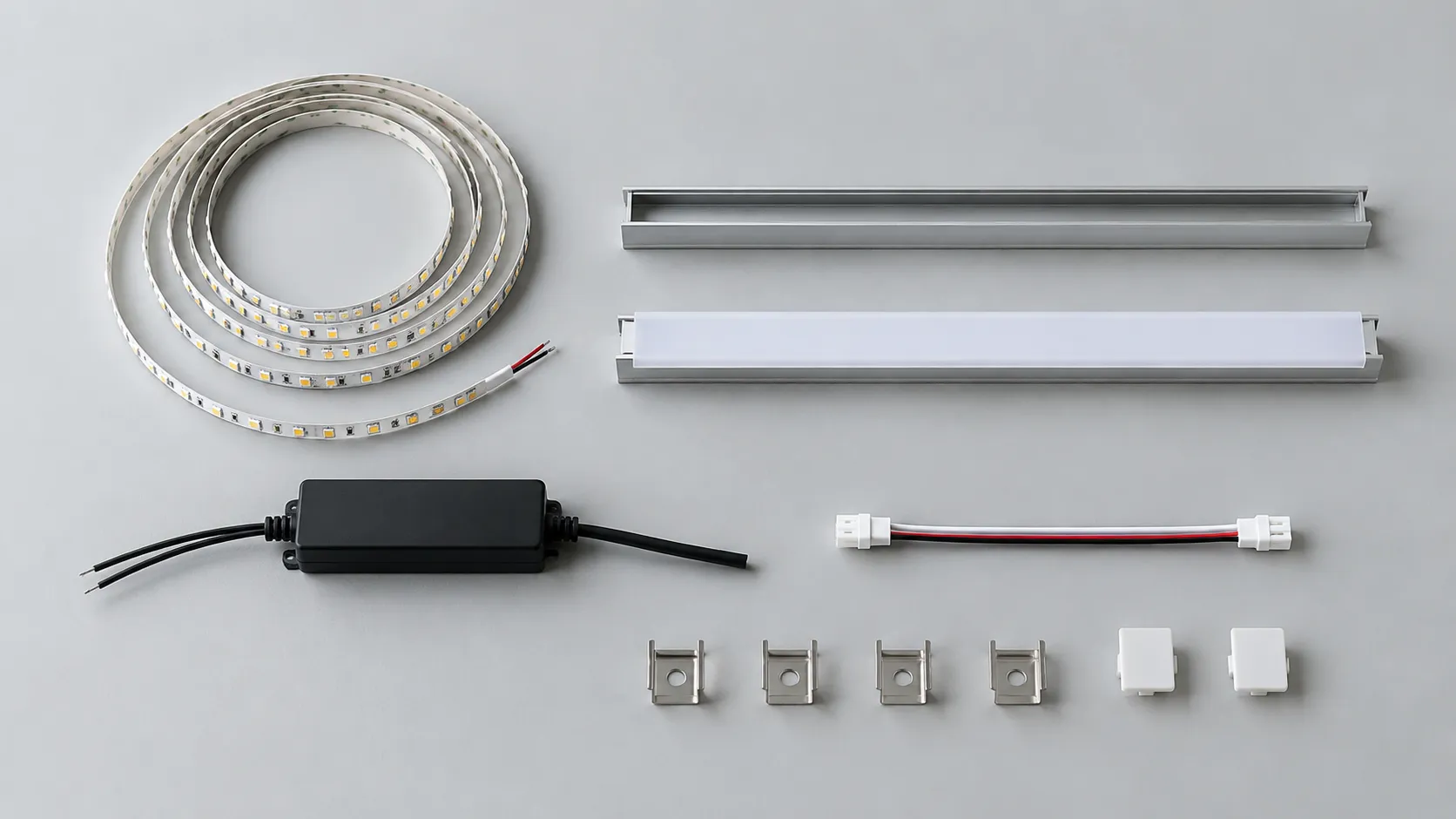
Have the ceiling line cut to your section, not to a reel length
We build LED strip in our own factory in Foshan, 4,000 square metres with 40 people across two production lines, so run lengths, feed positions, output per metre and pack contents are lines you write rather than a catalogue you pick from. Send the reflected ceiling plan, one fascia section and the space type, and we will quote the run.
Watch it work
Where the source hides, why the ceiling paint counts twice and what the corners give away, in 30 seconds:
FAQ
LED strip light ceiling design?
Treat it as a document rather than a look. A supplier can price a run from one section per placement plus the finish references, the metres per segment and a note on where a driver stays reachable; from a plan with a dashed line and a colour temperature, a supplier is guessing. Ask whether your drawing lets somebody else find the fault before the plaster goes on.
How do we stop the joint between two reels showing on a long line?
Plan the joints instead of discovering them. Ask for one production bin per run and say so on the purchase order, then decide before cutting which joints land at corners or above door heads where the eye is already busy. If a run must come from more than one lot, put the change at a physical break in the architecture rather than mid-ceiling.
Is a ceiling run worth building in a leased shell that gets refitted every few years?
Often not, and it is worth saying so before the tenant pays for plaster. A cove or a stepped drop is joinery and plasterwork with some tape in it, and the tape is the cheap part. On a short lease the same look is better bought as a surface-mounted profile that unscrews and travels to the next site.
Who supplies the fascia and the ledge, the lighting supplier or the builder?
Almost always the builder, which is exactly why the dimensions have to appear in the lighting documents. The lighting package delivers tape, extrusion, cover, drivers and cable; the ceiling contractor delivers the recess those things live in. Most sight line failures on handover photographs sit in that gap, where a plasterer worked to a plan and nobody sent the section across.
Sources
Every external figure above was checked on 2026-09-20: lighting power allowances and egress illumination from the adopted code text, flicker from the U.S. Department of Energy, the lifetime definition from ENERGY STAR, surface reflectances from the ASHRAE and IES design guides, end-use energy from the Energy Information Administration, the cove description from the standard reference entry, and the selection procedure from the peer-reviewed paper cited in full below.
- UpCodes, Interior Lighting Power Allowance, International Energy Conservation Code Tables C405.3.2(1) and C405.3.2(2) as adopted in Colorado (corridor 0.44 W/ft², lobby 0.80, retail sales area 0.85, bar or lounge dining 0.76, cafeteria or fast food dining 0.36, hotel or motel building-area method 0.53; one watt per square foot equals 10.76 W/m²), retrieved 2026-09-20.
- UpCodes, Illumination Level Under Normal Power, International Building Code section 1008.2.1 as adopted (means of egress illumination not less than 1 footcandle, 11 lux, at the walking surface; 10 footcandles, 108 lux, on exit access and exit stairways in use), retrieved 2026-09-20.
- U.S. Department of Energy, Solid-State Lighting Program, Flicker and temporal light modulation (direct flicker roughly 3 to 80 Hz; stroboscopic effects roughly 80 Hz to 1000 Hz; modulation still identified at 1000, 2000 and 6000 Hz where there is relative movement; LEDs have little thermal or phosphor persistence), retrieved 2026-09-20.
- ENERGY STAR, U.S. Environmental Protection Agency, Learn About LED Lighting (LED lifetime is established on a prediction of when light output decreases by 30 percent), retrieved 2026-09-20.
- LightNOW, Craig DiLouie, ASHRAE/IES Recommended Surface Reflectances, summarising the ASHRAE and IES Advanced Energy Design Guides (small retail ceiling 80%, wall 50%; office ceiling above 80%, and 90% if the lighting is indirect; hospital ceiling at least 90% where indirect), retrieved 2026-09-20.
- U.S. Energy Information Administration, Use of energy explained: energy use in commercial buildings (lighting accounted for about 10% of total commercial building energy use in 2018), retrieved 2026-09-20.
- Wikipedia, Cove lighting (indirect lighting built into ledges, recesses or curtain valances in a ceiling or high on the walls; minimum distance from the ceiling given as at least 18 inches, 46 cm, with the cove around 6 feet 8 inches, 2.03 m, from the floor), retrieved 2026-09-20.
- Zagan, W., Skarzynski, K. and Tryzna, G., The simplified equipment selection method for the cove lighting, Ain Shams Engineering Journal, 2023, volume 14, issue 10, article 102148, doi:10.1016/j.asej.2023.102148 (a procedure for selecting the luminous flux per metre of LED strip needed to reach a target average illuminance and uniformity in a room of known height and floor area), record checked 2026-09-20.
